7.20.2020

Project CBR600F: Red Lights and Flashers

My Amazon multi-function signals arrived and I made a trek to Tractor Supply Company to get an oval LED tail light and mount. I want everything to be LED to help conserve what little output the Hurricane's electrical system can pump out.  I originally shopped the net for an LED tail light but so many are not DOT approved and have bad reviews.  I'd really prefer to not have a dim, essentially useless tail light.  On AdvRider, I saw a KLR build where the guy used two oval trailer in a V formation and it gave me the inspiration for this project. 


The signals even came with a set of resistors.


As I mentioned, these are multi-function, tail or brake, and signal. I opted for signal and brake light as I'm not sure on the laws regarding red running lights on a motorcycle and I don't want them to distract from the actual brake light. I read some place that brake lights in a triangle formation are more attention grabbing, so yeah. 


Lookin' good from the rear.


The LED flasher module I need from SuperBrightLEDs is on back order, so I stopped by CycleGear and grabbed one from SpeedMetal.  After I purchased it, I noticed it was "specific" for you Yamaha.


You're not the boss of me sticker! I'm putting this on a Honda.


I was unsure if it would work since my OEM flasher has three wires.  The kind associate at CycleGear assured me I could return it if it didn't work.  Thankfully, it worked just fine! The OEM version has a dedicated ground, while the LED uses the ground from the light circuit. 


Overall, I'm really happy with how well this all turned out.  Everything fit just right and the wiring was simple. The running light is very bright and the combination of the brake light and brake function of the signals is very bright. In the future, I may add a tail light strobe like I put on my Ulysses. 

7.17.2020

Project CBR600F: Shining Light of Neutrality

With my custom dash in place and wired, I noticed two warning lights did not work, neutral and oil.  After some quick Googling, I found the common culprit is the neutral switch, located on the lower left side of the bike, just near the starter motor. 


The rubber cap snapped off when trying to remove it.


Removal is super easy, remove the 7mm nut and lock washer. Place an oil pan under the bike as you'll have some oil loss.  This sensor takes a 14mm socket / wrench.


Looking kinda crusty.  Be sure to clean up the contacts if needed.


The sensor tip rubs against the shift drum, so after a while, it wears away.


The sensor is a direct swap, don't forget your copper washer.  I stuck my broken cap back on with a healthy dose of red RTV.

With the sensor replaced, I hooked up my wiring and tested it.  But, no luck. Time to bust out the wiring diagram.  When I wired the neutral and oil lights, I wired them as if they were normal lights, like the brights or t-signals.  These sensors are the opposite, the power is constant, and the ground is switched.  I'm sure there's a name for this but, it's not in my electrical knowledge base (UPDATE: switched ground).  On these, the power is fed via the Black/Brown wire, and the other wire is the ground.

I did my best to try and remove the wiring from the block but it failed.  I ended up needing to replace the Oil LED light and rewire the rest.  To say these wires are thin is an understatement.


Hooray!


The next garage session will either be wiring up the tail light, rear signals and plate holder, or the swing arm.   To be continued....

7.06.2020

Project CBR600F: Trackside Heated Grip Kit

Back in 2011, I installed a set of Kimpex heated grips on my XJ600.  Ever since,  I can't live without toasty digits at the flick of a switch. Installing the grips is simple, I used the same manner as shown in the XJ installation post.

Remove your old grips, install the sticky backed heat elements, secure them with a few rings of 1" heat shrink tubing.   On the left grip, you may want to put a layer or two of tubing under the heat element to balance out the feel since it is inherently cooler than the throttle side.  Route the wiring, leaving enough slack on the throttle side as needed.

To keep from accidentally killing your battery when you leave your grips on (and you will forget), you'll want to power the grips via relay and distribution block.  I used a 5 pole relay, wired as shown.


The 87 pole will route power to the block when the relay is energized, 87A will have power when the relay is powered down.  For my installation I used 87A and a ground feed to connect to my SAE charging wire. That way I save on wiring mess, connections to my battery and the charging port is "dead" when the bike is running. Pole 86 is fed from the taillight wire. Pole 30 will need a fuse between the relay and the battery.  My drawing of the power block is not really accurate as the terminals are separated horizontally, instead of vertically as I drew it. But you get the idea. For future expansion of farkles, I went with two separate blocks.  Many moons ago, a friend had a low speed get off.  Thankfully he was ok but his bike started acting strange.  Honking, lights flashing, loss of power, then back to normal.  We eventually got it into the garage and it turned out to be a loose ground due to all the goods stacked on it.  So, moral of the story, use distribution blocks.


This aluminum sheet will be replaced with ABS, molded to fit.


Both blocks nestled in their new homes.


Wrapped up with quality electrical tape to add a level of weather proofing. 


Lookin' good!


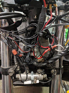
Find a suitable location for the switch ( I recommend buying a better quality switch with a water resistant cover). You'll need a SPDT (single pole dual throw) switch. For the CBR, I mounted the switch in the dash plate I fabricated.  The power feed connects to the middle pole.  Connect the wire with the resistor to one of the remaining poles, this is your HIGH setting.  The other is the LOW.  From here, select a wire from each element and connect both to the HIGH/LOW wire, single end.  The remaining wire from each element is for the ground.  Clean up your wiring and find a suitable location to mount the resistor. I used a hose clamp to mount to the brake block.  Is that the best? Maybe not, as it will get pretty toasty, so I may move it when I get my headlight assembly.

Definitely don't bundle it with wires unless you want to release the magic smoke from your harness.
My wiring is a bit messy as I'm also powering a USB power outlet on the backside of my dash plate.


I flipped the switch and was rewarded with warm digits. Hooray!

Update:

New ABS inner "fender" in place and distribution blocks attached with velcro strips.